IEC motor nameplates provide important information about the motor’s specifications and capabilities.
Here’s a short guide on how to read an IEC (International Electrotechnical Commission) motor nameplate.
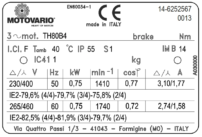
Three-phase motor nameplate
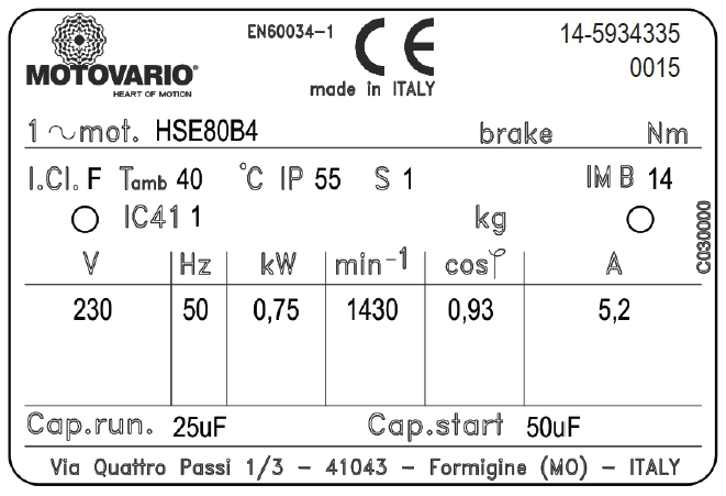
Single-phase motor nameplate
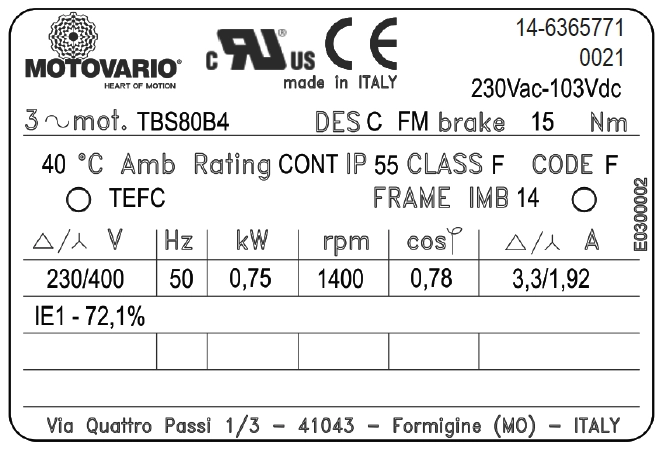
UL/CSA motor nameplate
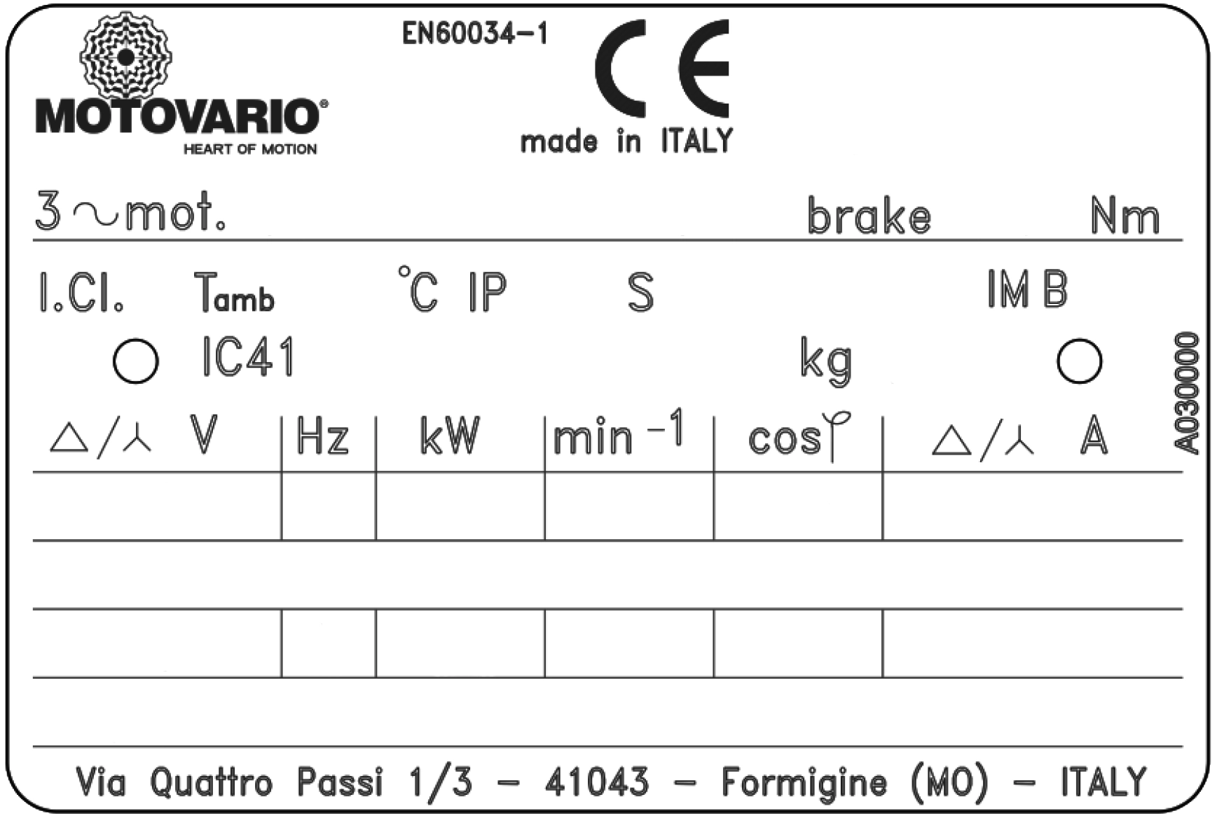
Manufacturer
Number of Phases
Rated Operating Voltage
Service Duty
Efficiency Code
Frame Size
Degree of Protection
Insulation Class
Temperature Rise
Frequency (Hz)
Motor Rated Power
Full Load Speed (RPM)
Rated Operating Current
Power Factor (PF)
Ambient Temperature
Service Factor
Altitude
Motor Weight
Brake Type (Brake Motors Only)
Nominal Braking Moment (Brake Motors Only)
Brake Power Supply(Brake Motors Only)
Identifies the company that manufactured the motor.
This indicates the type of power supply required for the motor’s operation, either single-phase or three-phase. Single-phase motors are typically used where only single-phase power is available, such as domestic based premises and agricultural applications. Three-phase motors are usually employed for every other scenario.
This specifies the optimal voltage at which the motor is designed to operate. This value is listed in volts (V). Most motors are designed to function within a ±10% tolerance range of the rated voltage. Other parameters displayed on the nameplate (power factor, efficiency, torque, and current) are based on the motor operating at the rated voltage and frequency. Using the motor outside the voltage tolerance range may lead to performance variations or potential issues.
The Service Duty, denoted as Duty/Time rating, specifies the duration a motor can operate safely at its nameplate rating or rated load. This parameter indicates whether the motor is suited for continuous duty. A “CONT” rating signifies continuous duty operation (24/7), while short-time ratings range from 5 to 60 minutes. Most motors are designed for continuous duty.
IEC standards classify motor duties into ten ratings based on the ambient temperature and the corresponding duration of operation. These ratings provide guidelines for safe operating conditions and help prevent motor overheating and damage.
Here is a brief breakdown of IEC duty ratings:
The Efficiency Code indicates the percentage of input power that is effectively converted into useful work output at the motor shaft. It represents the motor’s energy conversion efficiency.
The nameplate displays the “nominal” or average efficiency value. A higher efficiency rating closer to 100% results in lower electricity consumption costs.
IEC standards define four efficiency levels for three-phase induction motors:
IE1 – Standard Efficiency
IE2 – High Efficiency
IE3 – Premium Efficiency
IE4 – Super Premium Efficiency
The current legislation calls for a minimum efficiency of IE2 on motors <0.75kW, IE3 for motors sized 0.75kW > <75kW and IE4 75kW-250kW.
The Frame Size specifies the motor’s mounting dimensions, including foot-bolt pattern and shaft height. Frame sizes follow either the NEMA (National Electrical Manufacturers Association) or IEC (International Electrotechnical Commission) standards.
The Degree of Protection, represented by an Ingress Protection (IP) rating indicates the level of environmental protection provided by the motor’s enclosure.
For IEC motors, a two-digit IP rating is used:
Higher IP ratings signify better protection, with IP68 being the highest level of ingress protection.
To learn more about Ingress Protection/IP ratings, consult this article <link to IP rating article>
This represents the motor’s ability to withstand high temperatures over time, which can significantly impact its service life. The highest temperature at the motor’s hottest spot depends on the motor’s design temperature and the ambient temperature.
IEC standards specify five different insulation classes, each with a designated code letter and corresponding maximum temperature rating:
Class A – 105°C
Class E – 120°C
Class B – 130°C
Class F – 155°C
Class H – 180°C
A higher insulation class letter indicates a greater heat tolerance capability. For example, Class H insulation can withstand higher temperatures compared to Class B without degrading or reducing the motor’s lifespan.
Selecting the appropriate insulation class ensures the motor operates within its thermal limits, preventing premature insulation breakdown and extending its service life, especially in high-temperature environments or applications with frequent start-stop cycles.
In addition to the Insulation Class, motor nameplates may also specify Temperature Rise ratings, which are directly related to the winding insulation’s thermal capabilities.
The Temperature Rise rating consists of two components:
Both the Maximum Winding Temperature Rise and Hot Spot Temperature Rise are specified in degrees Celsius (°C) and must not exceed the limits defined by the motor’s Insulation Class.
Here are the temperature rise limits for each insulation class:
The Frequency (Hz) specifies the input electrical frequency at which the motor is designed to operate. Most motors are designed for either 50 Hz or 60 Hz input frequency.
If the nameplate lists multiple frequencies (e.g., 50/60 Hz), other performance parameters that vary with frequency, such as speed, power, and current, must also be indicated on the nameplate for each respective frequency.
Example:
Ensure the motor is operated at the specified frequency to maintain proper performance and prevent potential damage.
This value indicates the motor’s mechanical output rating, representing its ability to deliver the required torque to the load at the rated speed. The rated power is expressed in kilowatts (kW).
For example, a motor with a rated power of 5.5 kW is designed to provide a mechanical output power of 5.5 kilowatts at its rated speed and load conditions. Selecting a motor with an insufficient rated power may lead to overheating, reduced efficiency, and premature failure, while oversizing can result in unnecessary costs and inefficiencies.
The Full Load Speed, expressed as RPM (revolutions per minute) or min⁻¹, indicates the rotational speed of the motor shaft when operating at its rated full-load torque and rated power output. It is also known as the slip speed or actual rotor speed.
For induction motors, the full load speed is slightly lower than the synchronous speed due to inherent slip. Properly matching this speed to the application’s requirements ensures optimal motor performance, torque delivery, and compatibility.
Motor nameplates may display this speed using either “RPM” or “min⁻¹”, depending on regional conventions and standards. Always verify the full load speed to ensure the motor is suitable for the intended application and load characteristics, avoiding potential issues such as excessive vibration or insufficient torque.
This, expressed in amperes (A), corresponds to the motor’s rated power output, voltage, and frequency. This value represents the current the motor is designed to draw under full-load conditions.
However, the actual operating current may deviate from the nameplate value due to factors such as:
Indicated on the nameplate as “PF”, “P.F”, or “cos φ”, represents the ratio of active power (W) to apparent power (VA), expressed as a percentage or a value between 0 and 1.
Power Factor is a measure of how efficiently the motor converts electrical energy into useful mechanical work. A higher power factor (closer to 1 or 100%) indicates better energy conversion efficiency.
Example nameplate markings:
This, displayed as (AMB), specifies the highest surrounding temperature at which the motor can operate safely without exceeding the insulation class’s maximum temperature rise tolerance.
For example, if the (AMB) of the motor has a maximum ambient temperature of 40°C, this means the motor can operate in environments up to 40°C while maintaining safe temperature rise levels and preserving the insulation’s integrity.
Operating the motor in ambient temperatures higher than specified can lead to reduced lifespan, insulation failure, and potential motor damage. Motors can be derated for higher ambients and altitudes, but its best to ensure the motor is used within the recommended ambient temperature range for reliable and safe operation. i
This indicates the motor’s ability to handle temporary overload conditions beyond its rated power output. It represents the amount of overload a motor can withstand for short periods without sustaining damage or premature failure.
A motor with a Service Factor of 1.0 should not be operated above its nameplate rated power. However, a motor with a Service Factor of 1.15 can safely handle infrequent load demands up to 15% higher than its rated power for brief periods.
It is important to note that operating a motor continuously above its rated load, even within the service factor range, can lead to adverse effects such as reduced speed, overheating, decreased efficiency, reduced power factor and a shortened lifespan.
It is generally recommended to size motors for their intended continuous load requirements and avoid prolonged operation within the service factor range. The service factor should only be utilised for temporary overload conditions and not as a substitute for properly sizing the motor.
This shows the maximum height above sea level at which the motor can operate while staying within its design temperature rise and meeting all other nameplate data.
Below this altitude, the motor may run cooler; above this altitude the motor may run hotter, potentially leading to reduced performance, overheating, and decreased lifespan.,
This shows the weight of the motor
This shows the (unique) serial number of the motor.
When seeking technical support, providing the serial number helps identify the type of motor you have.
Betech 100pt Ltd
Four Square Buildings, Thomas Street, Heckmondwike,
West Yorkshire WF16 0LS
Registered in England No. 240 4937
VAT No. 461 3067 67
Betech Terms & Conditions
To view our updated terms and conditions of sale